本节代码地址github
1、Introduction 中断 是指来自外部设备的信号,给到CPU,例如键盘或者其他的硬件设备。CPU收到中断信号后不顾一切的停止正在执行的指令,转而去执行一些预先设定好的中断指令。
注意,中断指来自外部设备的信号,其他的比如除以0等问题来自于CPU内部,我们称之为异常(Exception)。
中断和异常本质上工作原理相同,只不过来源不同。本节我们也会涉及一些异常的内容。
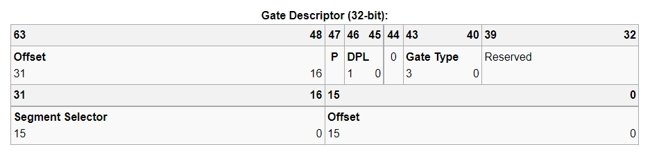
2、IDT 和GDT类似。IDT也是一种描述符表格,全称为Interrupt Descriptor Table 。IDT中的每一项叫做门描述符(Gate Descriptor),门描述符的数据结构如下图所示:
可以看到,IDT中有一部分为Segment Selector,段选择子的内容我们在GDT中讲过,负责选择GDT中的某个描述符,然后根据描述符中的内容获得基地址。这里也是同样的原理,由于中断是CPU停止现在的工作,转到执行一些预先设定好的指令,这些指令也存在内存中,一般在代码段中。通过IDT中的段选择子以及Offset我们可以跳转到要执行的中断指令处,这样就实现了中断。
IDT的其他部分内容如下所示:
Offset: A 32-bit value, split in two parts. It represents the address of the entry point of the Interrupt Service Routine Selector: A Segment Selector GDT Gate Type: A 4-bit value which defines the type of gate this Interrupt Descriptor represents. There are five valid type values:
0b0101 or 0x5 : Task Gate, note that in this case, the Offset value is unused and should be set to zero.0b0110 or 0x6 : 16-bit Interrupt Gate0b0111 or 0x7 : 16-bit Trap Gate0b1110 or 0xE : 32-bit Interrupt Gate0b1111 or 0xF : 32-bit Trap Gate
DPL: A 2-bit value which defines the CPU Privilege Levels INT instruction. Hardware interrupts ignore this mechanism.P: Present bit. Must be set (1 ) for the descriptor to be valid.
For more information, see Section 6.11: IDT Descriptors and Figure 6-2: IDT Gate Descriptors of the Intel Software Developer Manual, Volume 3-A.
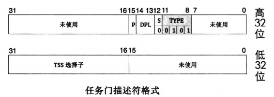
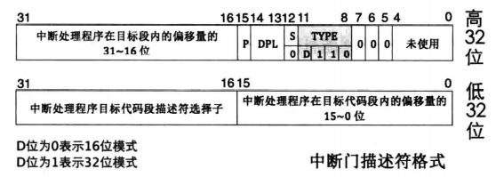
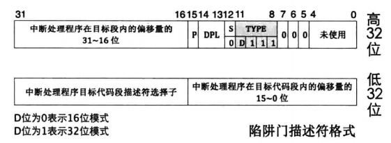
通过上面的描述我们可以看出,IDT中一共存在四种门描述符,分别是任务门、中断门、陷阱门以及调用门,这四种结构的具体内容如下:
任务门:
中断门:
陷阱门:
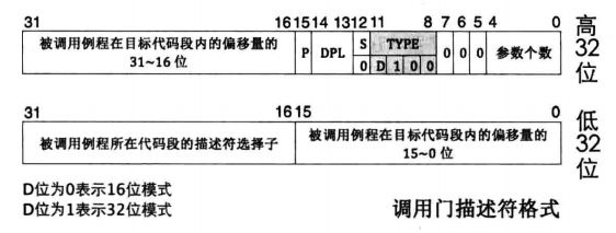
调用门:
可以看到,每种门的TYPE字段是不同的。另一个不同点是,任务们选择子字段是TSS选择子。TSS(Task Status Segment)是Intel处理器中提供任务切换机制时使用的数据结构。由于我们本次实现的操作系统不涉及TSS,所以这里不做展开讲述。
详细了解TSS可以参考《Linux内核完全剖析 -基于0.12内核》这本书的140页开始的boot.s以及head.s的讲解。
门描述符的定义如下:
1
2
3
4
5
6
7
8
9
struct GateDescriptor {uint16_t handleAddressLowBits;uint16_t gdt_codeSegementSelector;uint8_t reserved;uint8_t access;uint16_t handleAddressHighBits;static GateDescriptor interruptDescriptorTable[256 ];
处理器只支持256个中断,所以我们设置一个长度为256的数组来存放门描述符,也就是IDT
3、Where is IDT? 在GDT一节中我们介绍过,通过GDTR存储GDT的位置,这样访问GDTR我们就能找到GDT。
同样,IDT的地址存储在IDTR(Interrupt Descriptor Table Register)中,
没错,IDTR的结构也和GDTR非常类似,图中Offset存储着IDT的基地址,32位系统中基地址有32位,64位系统中基地址自然是64位。size表示IDT中门描述符的个数,在OSDEV中有这样一句:IDT can contain less than 256 entries, any entries that are not present (due to this or other reasons) will generate a General Protection Fault IDT should contain enough entries so that this fault (which is itself an interrupt vector) can be handled.
虽然我们可能用不到256个中断,但是这256个中断必须都存在,哪怕是什么都不执行也要存在。因为访问不存在的中断会引起General Protection Fault。
最后,我们使用LIDT指令将IDT地址加载到IDTR中
1 asm volatile ("lidt %0" : : "m" (idt))
4、How to find Gate Descriptor? 中断的发生由外部或者内部的信号出发,这里的信号包含中断号信息,系统通过这个中断号就可以找到对应的门描述符(当然还有很多其他的处理),然后就可以执行中断了,这里不需要我们做太多的处理。
和GDT不同,我们没有段选择子。
5、Coding 首先创建三个文件:interrupts.h,interrupts.cpp,interruptstubs.s
这里我们只实现Intel设计者设计的17个中断以及20个异常的程序,其他的内容理论上要有,但是我们控制处理器不访问其他的内容即可。
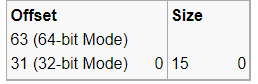
首先是interrupts.h,定义IDT
1
2
3
4
5
6
7
8
9
10
11
class InterruptManager {struct GateDescriptor {uint16_t handleAddressLowBits;uint16_t gdt_codeSegementSelector;uint8_t reserved;uint8_t access;uint16_t handleAddressHighBits;static GateDescriptor interruptDescriptorTable[256 ];
然后加载IDTR,填写IDT表
1
2
3
4
5
6
7
8
9
10
11
12
13
14
class InterruptManager {struct InterruptorDescriptorTablePointer {uint16_t size;uint32_t base;static void SetInterruptDescriptorTableEntry ( uint8_t interruptNumber, uint16_t codeSegmentSelectorOffset, void (*handler)(), uint8_t DescriptorPrivilegeLevel, uint8_t DescriptorType )
再然后设定需要完成的中断和异常处理指令,在cpp里面就是函数,这部分由interruptstubs.s实现
1
2
3
4
5
6
7
8
9
10
11
12
13
14
15
16
17
18
19
20
21
22
23
24
25
26
27
28
29
30
31
32
33
34
35
36
37
38
39
40
class InterruptManager {static void HandleInterruptRequest0x00 () static void HandleInterruptRequest0x01 () static void HandleInterruptRequest0x02 () static void HandleInterruptRequest0x03 () static void HandleInterruptRequest0x04 () static void HandleInterruptRequest0x05 () static void HandleInterruptRequest0x06 () static void HandleInterruptRequest0x07 () static void HandleInterruptRequest0x08 () static void HandleInterruptRequest0x09 () static void HandleInterruptRequest0x0A () static void HandleInterruptRequest0x0B () static void HandleInterruptRequest0x0C () static void HandleInterruptRequest0x0D () static void HandleInterruptRequest0x0E () static void HandleInterruptRequest0x0F () static void HandleInterruptRequest0x31 () static void HandleException0x00 () static void HandleException0x01 () static void HandleException0x02 () static void HandleException0x03 () static void HandleException0x04 () static void HandleException0x05 () static void HandleException0x06 () static void HandleException0x07 () static void HandleException0x08 () static void HandleException0x09 () static void HandleException0x0A () static void HandleException0x0B () static void HandleException0x0C () static void HandleException0x0D () static void HandleException0x0E () static void HandleException0x0F () static void HandleException0x10 () static void HandleException0x11 () static void HandleException0x12 () static void HandleException0x13 ()
最后,还有设定中断端口的指令,这部分内容后面会讲:
1 2 3 4 5 6 7 #include "port.h" class InterruptManager {
最后的最后,还有中断处理函数、中断激活和失效函数以及InterruptManager的构造函数、析构函数等
1
2
3
4
5
6
7
8
9
10
class InterruptManager {InterruptManager (GlobalDescriptorTable* gdt, uint16_t hardwareInterruptOffset);InterruptManager ();void Activate () void Deactivate () static uint32_t HandleInterrupt (uint8_t interruptNumber, uint32_t esp) uint32_t DoHandleInterrupt (uint8_t interruptNumber, uint32_t esp)
以上内容都是InterruptManager类中的内容,我们需要额外实现中断处理类,专门负责InterruptManager中的中断处理工作
1
2
3
4
5
6
7
8
9
10
11
class InterruptHandler {protected :InterruptHandler (uint8_t interruptNumber, InterruptManager* interruptManager);InterruptHandler ();uint8_t interruptNumber;public :uint32_t HandleInterrupt (uint32_t esp)
头文件定义完毕,接下来是实现:
interruptstubs.s实现了InterruptManager中的中断异常处理函数:
1
2
3
4
5
6
7
8
9
10
11
12
13
14
15
16
17
18
19
20
21
22
23
24
25
26
27
28
29
30
31
32
33
34
35
36
37
38
39
40
41
42
43
44
45
46
47
48
49
50
51
52
53
54
55
56
57
58
59
60
61
62
63
64
65
66
67
68
69
70
71
72
73
74
75
76
77
78
79
80
81
82
83
84
85
.set IRQ_BASE, 0x20 .section .text.extern _ZN16InterruptManager15HandleInterruptEhj.macro HandleInterruptRequest num.global _ZN16InterruptManager26HandleInterruptRequest\num\()Evjmp int_bottom.endm .macro HandleException num.global _ZN16InterruptManager19HandleException\num\()Evjmp int_bottom.endm 0x00 0x01 0x02 0x03 0x04 0x05 0x06 0x07 0x08 0x09 0x0A 0x0B 0x0C 0x0D 0x0E 0x0F 0x31 0x00 0x01 0x02 0x03 0x04 0x05 0x06 0x07 0x08 0x09 0x0A 0x0B 0x0C 0x0D 0x0E 0x0F 0x10 0x11 0x12 0x13 int_bottom: pusha push (interruptnumber)call _ZN16InterruptManager15HandleInterruptEhjpopa .global _ZN16InterruptManager15InterruptIgnoreEv_ZN16InterruptManager15InterruptIgnoreEv: iret .data interruptnumber: .byte 0
首先,_ZN16InterruptManager26HandleInterruptRequest\num\()Ev是我们通过objdump反汇编之后得到的名称,由于我们函数数量比较多,所以采用这种拼接的方式组成函数名称,这里建议观看参考资料 学习一下具体的命名方式。
下面说一下中断的处理方式,中断信号来到之后,CPU需要停止正在进行的工作,转而去执行中断指令。但同时需要考虑另一个问题,那就是执行完中断指令后要怎么办?那肯定是回到之前执行的工作继续执行啦。那怎么回去呢?寄存器就那么几个,肯定无法保存前面执行的内容,所以操作系统的实现者考虑使用栈来保存中断执行前的信息,中断执行之后再弹栈即可,这就是我们下面的中断执行函数的实现:
1 2 3 4 5 6 7 8 9 10 11 12 13 14 15 16 17 int_bottom:%ds %es %fs %gs %esp call _ZN16 InterruptManager15 HandleInterruptEhj%eax , %esp %gs %fs %es %ds
可以看到,每个中断或者异常处理函数都跳转到int_bottom,跳转之后开始压栈,然后执行InterruptManager::HandleInterrupt()函数。执行完毕后再弹栈,继续前面被终止的工作。
最后解释一下:
前面提到过,中断是由硬件发来的信号。CPU内部的“中断”叫做异常。操作系统设计者对这些内容编号时,设定了32个异常,排在前32位,后面紧接着就是中断,所以说我们的中断号是从32开始的,也就是0x20。意思就是,我们的第一号中断对应的中断编号位0x20+0x1
注:当我们提到中断号时就泛指所有的中断和异常。
最后是interrupts.cpp
首先是中断激活以及失效函数,sti指set interrupt,用于开启中断,cli指clear interrupt,用于清空中断。
ActiveInterruptManager指当前激活的InterruptManager对象,很明显,我们的中断请求由这个对象来处理。但这种中断处理对象不能存在多个,所以我们需要将其他的InterruptManager对象关闭掉,然后使用新的ActiveInterruptManager来处理中断。
1
2
3
4
5
6
7
8
9
10
11
12
13
14
void InterruptManager::Activate () if (ActiveInterruptManager != 0 ){Deactivate ();this ;asm ("sti" );void InterruptManager::Deactivate () if (ActiveInterruptManager == this ){0 ;asm ("cli" );
接下来就是中断处理,这里为了清晰明了作者(wyoos的作者)采用了两个函数来实现:
1
2
3
4
5
6
7
8
9
10
11
12
13
14
15
16
17
18
19
20
21
22
23
24
25
uint32_t InterruptManager::HandleInterrupt (uint8_t InterruptNumber, uint32_t esp) if (ActiveInterruptManager != 0 ){return ActiveInterruptManager->DoHandleInterrupt (InterruptNumber, esp);return esp;uint32_t InterruptManager::DoHandleInterrupt (uint8_t InterruptNumber, uint32_t esp) if (handlers[InterruptNumber] != 0 ){HandleInterrupt (esp);else if (InterruptNumber != hardwareInterruptOffset){char * foo = (char *)"UNHANDLED INTERRUPT 0X00" ;const char * hex = "0123456789ABCDEF" ;22 ] = hex[(InterruptNumber >> 4 ) & 0x0f ];23 ] = hex[InterruptNumber & 0x0f ];printf ((const char *)foo);if (hardwareInterruptOffset <= InterruptNumber && InterruptNumber < hardwareInterruptOffset + 16 ){Write (0x20 );if (hardwareInterruptOffset + 8 <= InterruptNumber){Write (0x20 );return esp;
HandleInterrupt判断是否存在前面所说的ActiveInterruptManager对象,如果不存在,自然不能执行中断
DoHandleInterrupt则是执行中断,这里我们采用打印相应的中断号作为中断处理程序,这样比较明显。
我们可以看到判断if(handlers[InterruptNumber] != 0),这里是为了我们后面实现键盘和鼠标做准备,我们设定好的中断自然有其自己的执行程序,而未设定好的中断则是采用打印UNHANDLED INTERRUPT 0X+中断号来实现的。其中,中断号0x20(第一个硬件中断)是指时钟中断,时时刻刻都在发生,所以我们将其屏蔽掉。
最后的判断是指8259A芯片编程,对硬件端口写入一些特定值,从而告知硬件中断已经处理完成。
接下来:
1
2
3
4
5
6
7
8
9
10
11
12
13
14
void InterruptManager::SetInterruptDescriptorTableEntry ( uint8_t interruptNumber, uint16_t codeSegmentSelectorOffset, void (*handler)(), uint8_t DescriptorPrivilegeLevel, uint8_t DescriptorType) const uint8_t IDT_DESC_PRESENT = 0x80 ;uint32_t )handler) & 0xffff ;uint32_t )handler >> 16 ) & 0xffff ;3 ) << 5 ) | DescriptorType;0 ;
设定门描述符,每处设定都是按照前面的门描述符的结构设定的,大家可以去对应一下。后面会不断调用这个门描述符表,毕竟有256个中断。
再然后:
1 2 3 4 5 6 7 8 9 10 11 12 13 14 15 16 17 18 19 20 21 22 23 24 25 26 27 28 29 30 31 32 33 34 35 36 37 38 39 40 41 42 43 44 45 46 47 48 49 50 51 52 53 54 55 56 57 58 59 60 61 62 63 64 65 66 67 68 69 70 71 72 73 74 75 InterruptManager::InterruptManager (GlobalDescriptorTable* gdt, uint16_t hardwareInterruptOffset)picMasterCommand (0x20 ),picMasterData (0x21 ),picSlaveCommand (0xA0 ),picSlaveData (0xA1 )this ->hardwareInterruptOffset = hardwareInterruptOffset;uint16_t codeSegemnt = gdt->CodeSegmentSelector ();const uint8_t IDT_INTERRUPT_GATE = 0xe ;for (uint16_t i=0 ; i<256 ; i++){0 ;SetInterruptDescriptorTableEntry (i, codeSegemnt, &InterruptIgnore, 0 , IDT_INTERRUPT_GATE);SetInterruptDescriptorTableEntry (0x00 , codeSegemnt, &HandleException0x00, 0 , IDT_INTERRUPT_GATE);SetInterruptDescriptorTableEntry (0x01 , codeSegemnt, &HandleException0x01, 0 , IDT_INTERRUPT_GATE);SetInterruptDescriptorTableEntry (0x02 , codeSegemnt, &HandleException0x02, 0 , IDT_INTERRUPT_GATE);SetInterruptDescriptorTableEntry (0x03 , codeSegemnt, &HandleException0x03, 0 , IDT_INTERRUPT_GATE);SetInterruptDescriptorTableEntry (0x04 , codeSegemnt, &HandleException0x04, 0 , IDT_INTERRUPT_GATE);SetInterruptDescriptorTableEntry (0x05 , codeSegemnt, &HandleException0x05, 0 , IDT_INTERRUPT_GATE);SetInterruptDescriptorTableEntry (0x06 , codeSegemnt, &HandleException0x06, 0 , IDT_INTERRUPT_GATE);SetInterruptDescriptorTableEntry (0x07 , codeSegemnt, &HandleException0x07, 0 , IDT_INTERRUPT_GATE);SetInterruptDescriptorTableEntry (0x08 , codeSegemnt, &HandleException0x08, 0 , IDT_INTERRUPT_GATE);SetInterruptDescriptorTableEntry (0x09 , codeSegemnt, &HandleException0x09, 0 , IDT_INTERRUPT_GATE);SetInterruptDescriptorTableEntry (0x0A , codeSegemnt, &HandleException0x0A, 0 , IDT_INTERRUPT_GATE);SetInterruptDescriptorTableEntry (0x0B , codeSegemnt, &HandleException0x0B, 0 , IDT_INTERRUPT_GATE);SetInterruptDescriptorTableEntry (0x0C , codeSegemnt, &HandleException0x0C, 0 , IDT_INTERRUPT_GATE);SetInterruptDescriptorTableEntry (0x0D , codeSegemnt, &HandleException0x0D, 0 , IDT_INTERRUPT_GATE);SetInterruptDescriptorTableEntry (0x0E , codeSegemnt, &HandleException0x0E, 0 , IDT_INTERRUPT_GATE);SetInterruptDescriptorTableEntry (0x0F , codeSegemnt, &HandleException0x0F, 0 , IDT_INTERRUPT_GATE);SetInterruptDescriptorTableEntry (0x10 , codeSegemnt, &HandleException0x10, 0 , IDT_INTERRUPT_GATE);SetInterruptDescriptorTableEntry (0x11 , codeSegemnt, &HandleException0x11, 0 , IDT_INTERRUPT_GATE);SetInterruptDescriptorTableEntry (0x12 , codeSegemnt, &HandleException0x12, 0 , IDT_INTERRUPT_GATE);SetInterruptDescriptorTableEntry (0x13 , codeSegemnt, &HandleException0x13, 0 , IDT_INTERRUPT_GATE);SetInterruptDescriptorTableEntry (hardwareInterruptOffset + 0x00 , codeSegemnt, &HandleInterruptRequest0x00, 0 , IDT_INTERRUPT_GATE);SetInterruptDescriptorTableEntry (hardwareInterruptOffset + 0x01 , codeSegemnt, &HandleInterruptRequest0x01, 0 , IDT_INTERRUPT_GATE);SetInterruptDescriptorTableEntry (hardwareInterruptOffset + 0x02 , codeSegemnt, &HandleInterruptRequest0x02, 0 , IDT_INTERRUPT_GATE);SetInterruptDescriptorTableEntry (hardwareInterruptOffset + 0x03 , codeSegemnt, &HandleInterruptRequest0x03, 0 , IDT_INTERRUPT_GATE);SetInterruptDescriptorTableEntry (hardwareInterruptOffset + 0x04 , codeSegemnt, &HandleInterruptRequest0x04, 0 , IDT_INTERRUPT_GATE);SetInterruptDescriptorTableEntry (hardwareInterruptOffset + 0x05 , codeSegemnt, &HandleInterruptRequest0x05, 0 , IDT_INTERRUPT_GATE);SetInterruptDescriptorTableEntry (hardwareInterruptOffset + 0x06 , codeSegemnt, &HandleInterruptRequest0x06, 0 , IDT_INTERRUPT_GATE);SetInterruptDescriptorTableEntry (hardwareInterruptOffset + 0x07 , codeSegemnt, &HandleInterruptRequest0x07, 0 , IDT_INTERRUPT_GATE);SetInterruptDescriptorTableEntry (hardwareInterruptOffset + 0x08 , codeSegemnt, &HandleInterruptRequest0x08, 0 , IDT_INTERRUPT_GATE);SetInterruptDescriptorTableEntry (hardwareInterruptOffset + 0x09 , codeSegemnt, &HandleInterruptRequest0x09, 0 , IDT_INTERRUPT_GATE);SetInterruptDescriptorTableEntry (hardwareInterruptOffset + 0x0A , codeSegemnt, &HandleInterruptRequest0x0A, 0 , IDT_INTERRUPT_GATE);SetInterruptDescriptorTableEntry (hardwareInterruptOffset + 0x0B , codeSegemnt, &HandleInterruptRequest0x0B, 0 , IDT_INTERRUPT_GATE);SetInterruptDescriptorTableEntry (hardwareInterruptOffset + 0x0C , codeSegemnt, &HandleInterruptRequest0x0C, 0 , IDT_INTERRUPT_GATE);SetInterruptDescriptorTableEntry (hardwareInterruptOffset + 0x0D , codeSegemnt, &HandleInterruptRequest0x0D, 0 , IDT_INTERRUPT_GATE);SetInterruptDescriptorTableEntry (hardwareInterruptOffset + 0x0E , codeSegemnt, &HandleInterruptRequest0x0E, 0 , IDT_INTERRUPT_GATE);SetInterruptDescriptorTableEntry (hardwareInterruptOffset + 0x0F , codeSegemnt, &HandleInterruptRequest0x0F, 0 , IDT_INTERRUPT_GATE);SetInterruptDescriptorTableEntry (hardwareInterruptOffset + 0x31 , codeSegemnt, &HandleInterruptRequest0x31, 0 , IDT_INTERRUPT_GATE);Write (0x11 );Write (0x11 );Write (hardwareInterruptOffset);Write (hardwareInterruptOffset + 0x8 );Write (0x04 );Write (0x02 );Write (0x01 );Write (0x01 );Write (0x00 );Write (0x00 );256 * sizeof (GateDescriptor) - 1 ;uint32_t )interruptDescriptorTable;asm volatile ("lidt %0" : : "m" (idt))
InterruptManager的构造函数,主要是构造IDT以及开启8259芯片,8259芯片的问题我们放在后面讲。这里主要数一下构造IDT
首先,硬件offset为0x20,设定好256个空的门描述符。
由于我们设定好了17个中断以及20个异常,所以分别将我们设定好的内容填入到IDT中,这样在执行中断时,遇到我们设定好的中断号,就会执行相应设定好的函数,为设定的中断号则执行InterruptIgnore,这个函数可以去interruptstubs.s中查看,本质上什么都没看,就一个函数名。最后我们设定IDTR,将中断描述符数量以及IDT基地址加载进去。
前面说过,InterruptManager中的中断处理交由InterruptHandler来实现,在InterruptManager中也设定好256个中断处理数组
1 InterruptHandler* handlers[256 ];
这样我们就可以执行相应的中断了。
结合前面的DoHandleInterrupt函数我们可知,当相应的中断号传输过来之后,我们首先判断是否有相应的中断处理函数(这些中断处理函数是我们提前设定好的,比如键盘、鼠标),如果有,则去执行相应的中断,如果没有,则是打印UNHANDLED INTERRUPT 0X+中断号
这就是当前我们的处理逻辑,后续我们实现键盘以及鼠标中断之后,只需要继承InterruptHandler,然后在InterruptManager中的handlers数组中添加相应的内容即可。
6、串联一下 如何实现中断?
首先,设定好IDT以及IDTR;
然后,实现InterruptManager以及InterruptHandler类,InterruptHandler包含在InterruptManager中,负责处理中断
最后,中断触发,产生相应的中断号,系统根据中断号找到对应的中断处理函数,完成中断处理
7、8259A !!!本篇重点,干货满满
首先列出参考资料
资料1
资料2
资料3
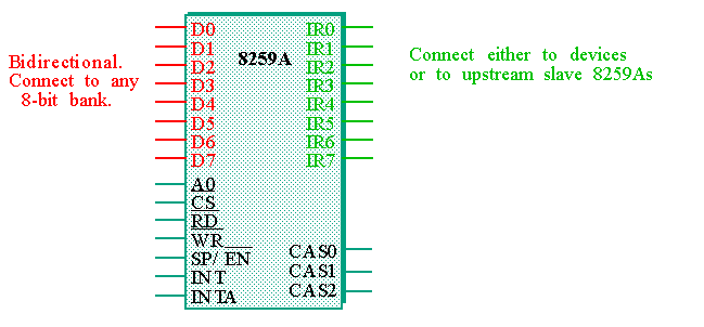
8259芯片是x86体系结构中最重要的芯片之一,8259A芯片的主要功能是管理硬件中断并且发送中断信号去执行。
8259A的原理图如下:
其中的IR0到IR7与外部设备链接,每个管脚代表一种中断,中断信号就是从这里传输进来的。
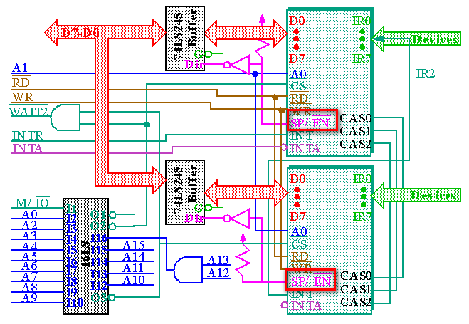
由于8个中断无法满足操作系统的需求,设计者又增加了一块8259A芯片,我们称第一块芯片为主芯片(Master),第二块芯片为从芯片(Slave)。从芯片连接在主芯片的IR2管脚,如下图所示:
这样就扩展为15条中断,足够操作系统使用。
学习过中断的朋友们知道中断也是存在优先级的,高优先级的中断来会优先执行高优先级的内容。8259A芯片管脚从0-7中断优先级逐级下降,所以我们硬件中断的优先级IR0 > IR1 > IR8 > IR9 > …… > IRC > IR3 > … > IR7,IR2也存在,但不是独立存在,而是成为了从芯片的入口。
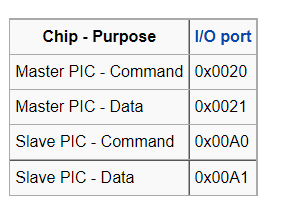
8259A存在两个端口,分别是指令端口(command)以及数据端口(data)为了控制8259A的主从芯片,操作系统设计者将两块芯片分别连接在如下端口中:
看着是不是有些熟悉了,这就是我们在InterruptManager类的构造函数中设置的四个值。
我们通过对这四个端口的操作,就可以使8259A芯片正常工作。
7.1、初始化命令字 此处参考资料2 ,非常感谢!大家给这个姐姐点个赞!
在8259A可以正常工作之前,必须首先设置初始化命令字 ICW (Initialization Command Words)寄存器组的内容。而在其工作过程中,则可以使用写入操作命令字 OCW (Operation Command Words)寄存器组来随时设置和管理8259A的工作方式。
观察8259A芯片管脚,存在一个A0端口,这个端口负责控制选择操作的寄存器当A0=0时芯片的端口地址是0x20(主芯片)和0xA0(从芯片);当 A0=1时端口就是0x21(主芯片)和0xA1(从芯片)。
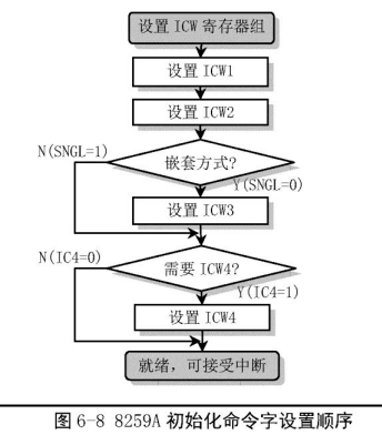
初始化命令字的编程操作流程如下图所示。由图可以看出,对 ICW1和 ICW2 的设置是必需的。而只有当系统中包含多片 8259A 芯片并且是级联的情况下才需要对 ICW3 进行设置。这需要在 ICW1 的设置中明确指出。 另外,是否需要对 ICW4 进行设置也需要在 ICW1 中指明。
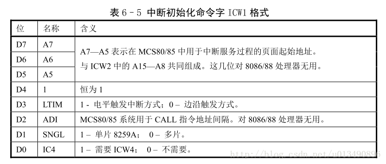
7.2、ICW1 当发送的字节第 5 比特位(D4)=1,并且地址线 A0=0 时,表示是对 ICW1 编程。此时对于 PC/AT 微机系统的多片级联情况下,8259A 主芯片的端口地址是 0x20,从芯片的端口地址是 0xA0。
ICW1表格如下:
我们向ICW1中写入0x11,表示中断请求是边沿触发、多片 8259A 级联并且需要发送 ICW4。
1 2 picMasterCommand.Write (0x11 );Write (0x11 );
根据流程图,接下来我们需要设定ICW2
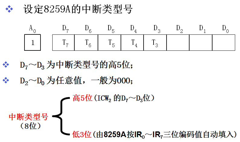
7.3、ICW2 ICW2 用于设置芯片送出的中断号的高5位。在设置了 ICW1 之后,当 A0=1 时表示对 ICW2 进行设置。此时对于PC/AT微机系统的多片级联情况下,8259A主芯片的端口地址是0x21,从芯片的端口地址是0xA1。
ICW2 格式如下:
ICW2 用于设置芯片送出的中断号的高5位。在设置了 ICW1 之后,当 A0=1 时表示对 ICW2 进行设置。此时对于PC/AT微机系统的多片级联情况下,8259A主芯片的端口地址是0x21,从芯片的端口地址是0xA1。
我们的硬件中断是从0x20开始的,每个芯片可以相应8个中断,所以主芯片0x20-0x27,从芯片0x28-0x30。ICW2设定主从芯片的起始中断号,后面的内容由芯片自行填入,所以我们将两块芯片的起始终端号填入0x20以及0x28即可。由因为ICW2只读取终端号的高5位,后面3位置0,而0x20和0x28后3位恰好都是0,所以我们将0x20和0x28写入对应端口即可。这门看来中断号的设置并不是随意设置的,而是和每种芯片的工作原理也是相结合着设定的。
1 2 picMasterData.Write (hardwareInterruptOffset);Write (hardwareInterruptOffset + 0x8 );
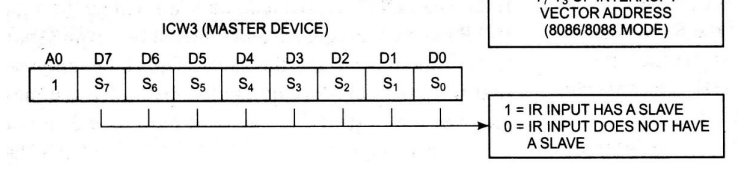
7.3、ICW3 观察ICW1的第一位SNGL=0,表示需要级联芯片,根据流程图可以看出我们需要设置ICW3
地址线A0=1,主芯片的端口地址是0x21,从芯片的端口地址是0xA1。
ICW3 (for master device) indicates where the slave is connected to the master.
ICW3 (for slave device) indicates where the slave is connected to the master
若8259为主片,ICW3用于指示哪个管脚与从片相连
哪一位为1,表明哪一位上有从片相连,
IR2和从片相连则ICW3为00000100,即0x04
IR6和从片相连则ICW3为01000000,即0x40
若8259为从片,ICW3用于指示从片与主片的哪个引脚相连
相连的内容由后三位指示,高五位置零
和IR2相连则后三位为010,即0x02
和IR6相连则后三位为110,即0x06
所以我们要向主片中写入0x04,从片中写入0x02
1 2 picMasterData.Write (0x04 );Write (0x02 );
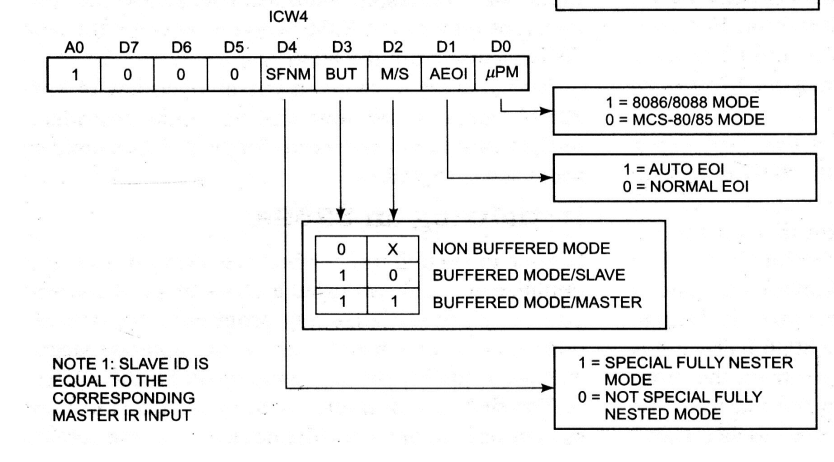
7.4、ICW4 ICW1的第0位为1,表示需要设置ICW4
地址线A0=1,主芯片的端口地址是0x21,从芯片的端口地址是0xA1。
换一张中文图:
我们向主从芯片中分别写入0x01,表示 8259A 芯片被设置成普通全嵌套、非缓冲、非自动结束中断方式,并且用于 8086 及其兼容系统。
1 2 picMasterData.Write (0x01 );Write (0x01 );
8、操作命令字 在对 8259A 设置了初始化命令字后,芯片就已准备好接收设备的中断请求信号了。但在 8259A 工作期间,我们也可以利用操作命令字 OCW1~OCW3 来监测 8259A 的工作状况,或者随时改变初始化时设定的 8259A 的工作方式。
需要说明的是,与初始化命令字ICW1~ICW4需要按规定的顺序进行设置不同,操作命令字OCW1~OCW3的设置没有规定其先后顺序,使用时可根据需要灵活选择不同的操作命令字写入到8259A中。
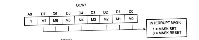
8.1、OCW1 OCW1 用于对 8259A 中中断屏蔽寄存器 IMR 进行读/写操作。地址线A0=1
若 $M_i=1$,则屏蔽对应中断请求级${IR}_i$;若$M_i=0$,则允许${IR}_i$. 另外,屏蔽高优先级并不会影响其他低优先级的中断请求。
这里由于我们不需要屏蔽任何的中断(时钟中断我们只是不做处理,而不是屏蔽,所以在这里不需要设置),所以我们向其中传入0x0
1 2 picMasterData.Write (0x00 );Write (0x00 );
8.2、OCW2 由于ICW4中第1位AEOI我们设定为非自动结束方式,所以在执行中断之后,我们需要手动输入某些内容告诉8259A 中断已经结束。
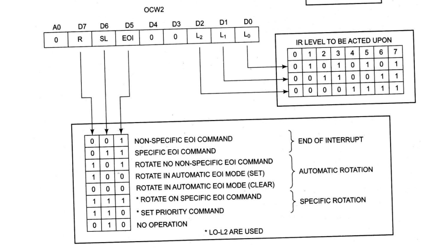
这就使用到了OCW2
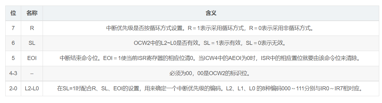
这里是具体OCW2各位表示的内容
Linux-0.11 内核仅使用该操作命令字在中断处理过程结束之前向 8259A 发送结束中断(EOI)命令。所使用的OCW2 值为 0x20,表示固定优先级、一般EOI(对应上表的第一行)。
也就是DoHandleInterrupt中的
1 2 3 4 picMasterCommand.Write (0x20 );if (hardwareInterruptOffset + 8 <= InterruptNumber){Write (0x20 );
这里的判断是在判断从片是否在使用,无论从片是否使用,主片都需要写入0x20
8.3、OCW3 再次感谢姐姐
9、总结 本节内容较多,大家应该结合代码和视频参考资料多多学习,本人也是反复研究之后才写出这篇文章!